Modelling and Analysis of Paste Flow and Segregation in High Performance Søderberg Electrodes
- Researcher: Alissa Kamilova

- Academic Supervisors: Ian Hewitt and Peter Howell
- Industrial Supervisors: Ben Sloman, Aasgeir Valderhaug, Bjørnar Larsen
Background
Søderberg electrodes are the most commonly used electrode system in submerged-arc furnaces for ferroalloys, platinum smelting, and slag cleaning operations. The paste is the raw material that makes the electrodes. It is fed at a constant rate into the top of a cylindrical steel tube (of diameter of up to 2 m) in the form of cylinders (of diameter of up to 1m), or smaller briquettes or blocks. Heat is supplied by fans blowing hot air along the walls, and induced in the steel tube by the current supplied by the copper tubes. A schematic of the electrode is shown in the denoted Target Situation in Figure 1 below.
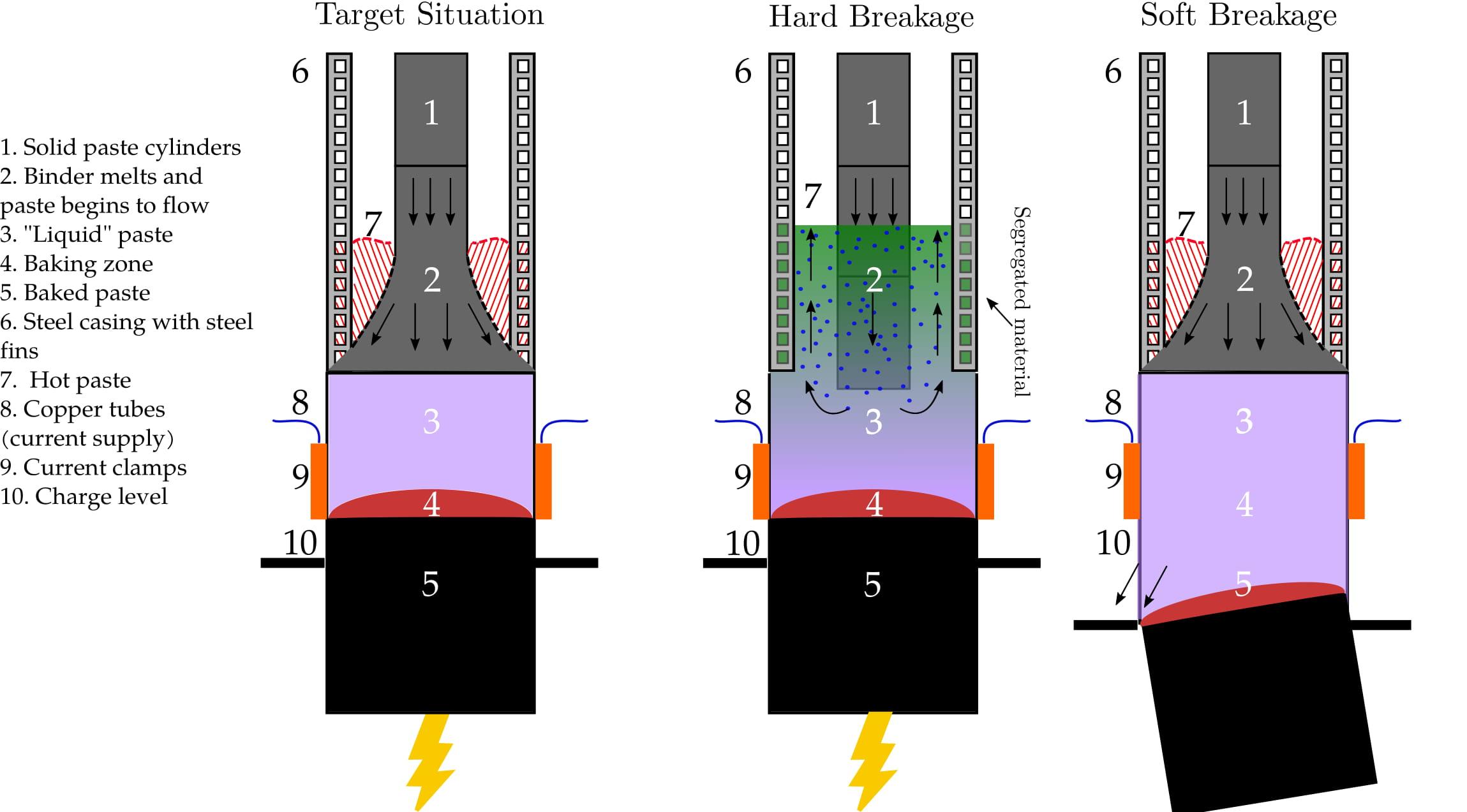
Figure 1: A schematic of the Søderberg electrode, in a target situation, soft, and hard breakage.
Throughout the years, demand has required electrode sizes and equipment to be changed, which has led to an imbalance in the melting process, making the cylinders sink down into the liquid paste, which results in an electrode with non-uniform material properties. The consequences of this may in some cases be disastrous, resulting in soft breakages, fires, and explosions. Examples of these breakages are also shown in Figure 1, where a hard breakage occurs when the cylinders sink down instead of softening, and a soft breakage occurs when the paste does not bake properly, breaking off at the clamps area.
Elkem are interested in understanding the ideal operating conditions for the electrode so that the paste will have the correct softening profile. Our aim is to make a mathematical model for the melting of the cylinders to understand how this process works. In particular, if we look at the Target Situation in Figure 1, we focus on the top part of the electrode, and wish to describe how the paste cylinders deform and touch the casing, indicated by the dashed black line, as well as the effects of the hot paste in this region, shown by the dashed red line and the shaded red region.
Outcomes
We have developed two main models to explain the behaviour of the paste at the top of the electrode. The first is a simple 1D axisymmetric model for one phase fluid flow and temperature. Our focus was on the behaviour of the paste where it begins to soften until it reaches the casing and behaves as a plug flow.
First, we obtained steady-state solutions and we computed the position of the free boundary, called $\lambda$, where the paste reaches the casing for the first time.
The non-dimensional parameters for this model are:
- Stokes number (${\rm St}$): the ratio between gravitational and viscous forces, which determines how important the weight of the material at the top is with respect to the strength of the paste;
- Péclet number (${\rm Pe}$): the ratio between the convection due to paste movement and the conduction, and
- Biot number (${\rm Bi}$): the ratio between the convection due to heating from the sides and the convection due to paste movement.
We varied these parameters to better understand the behaviour of the paste, as seen in Figure 2, where we note that the larger the value of St, the smaller $\lambda$ is, i.e. the more readily the paste deforms and the sooner it makes contact with the casing. In this model, we identify a catastrophic failure of the process, e.g. a breakage, when $\lambda$ becomes 1, as this implies that the paste has not reached the casing in the designated area, preventing it from baking properly in the region below our model.
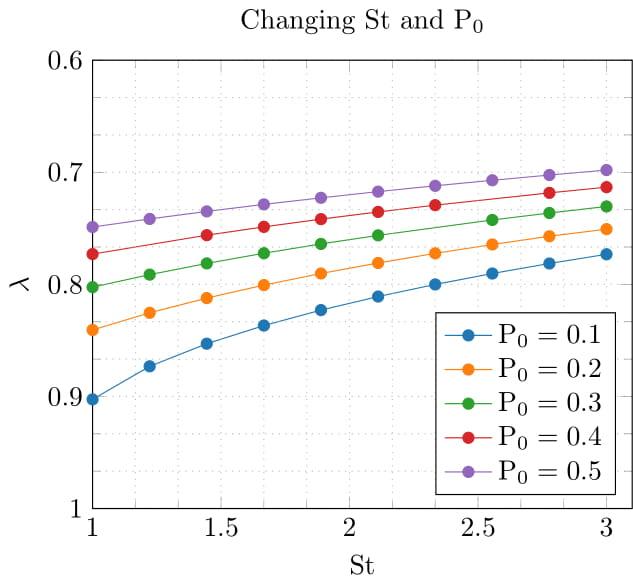
Figure 2: Effects on the free boundary $\lambda$ as we change Stokes number ${\rm St}$ and the applied compressive load, $P_0$.
When we look at Figure 3, we note that for large ${\rm Pe}$, the paste reaches the casing unless ${\rm Bi}$ is also large, indicating that we can reasonably simplify our problem assuming ${\rm Pe}$ is large, provided we keep ${\rm Bi}$ small. This also highlights the importance of the hot air heating present at the casing wall, which helps deform the paste so that $\lambda$ is reached in our domain of interest.
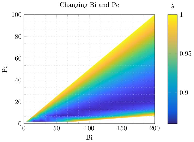
Figure 3: Effects on the free boundary $\lambda$ as we change the Biot number (Bi) and the Péclet number (Pe).
We also used the steady state solutions as a stepping point towards the dynamical case, where now the free boundary $\lambda$ varies with time. This allowed us to examine different control strategies for the addition of paste cylinders and how this affects the movement of $\lambda(t)$. We show examples of this in Figure 4, where we compare a set pattern of cylinder addition with a constant addition rate, and note how $\lambda(t)$ is affected by this transient behaviour. Adding cylinders per day, as opposed to keeping $P_0$ constant, causes $\lambda$ to move up and down, with it being closer to the inlet as more cylinders are added. However, if we look at the dashed lines in this figure, we also see that the predicted free boundary position for the steady state is expected further up the domain than the time dependent cases, indicating that transient behaviour is essential in order to understand the softening of the paste, as the variations between the days affect where the paste touches the casing and change the outcome. Further studies with this model include the development of control systems that return a cylinder addition regime such that the paste is kept at a specific level, for a given slipping velocity and cylinder size.
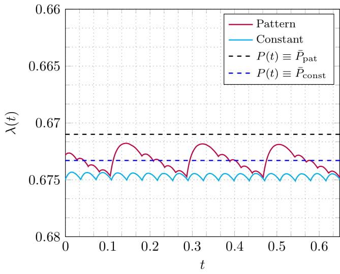
Figure 4: Effects on the free boundary $\lambda$ as we add cylinders at a daily rate, both following a pattern and with constant rate. We compare this to the dashed lines, which show the steady state solution for $\lambda$ as we use a constant $P_0$ instead of daily variation.
The second model developed in this project is a steady state hybrid extensional flow and lubrication theory fluid and temperature model, where we study the effects of the extreme viscosity variation of the paste on the behaviour of the flow. The resulting scaling process returns the same model parameters as before, namely ${\rm Pe}$, ${\rm Bi}$, and ${\rm St}$. Although here we do not track the free boundary $\lambda$, we do consider the interaction between the cylinders added and the hot paste on the sides of the casing, shown in the red dashed region of the electrode schematic in Figure 1. We show the numerical results of this approach in Figure 5, where the black lines are the streamlines of the flow, and the contours correspond to the magnitude of the velocity, for imposed quadratic temperature. We observe that as the paste cylinders are added, they displace the hotter paste present in the electrode, creating recirculating regions observed near the wall. In this example we do not solve for the temperature, but a full coupled temperature and flow problem has been solved and analysed in detail during the project.
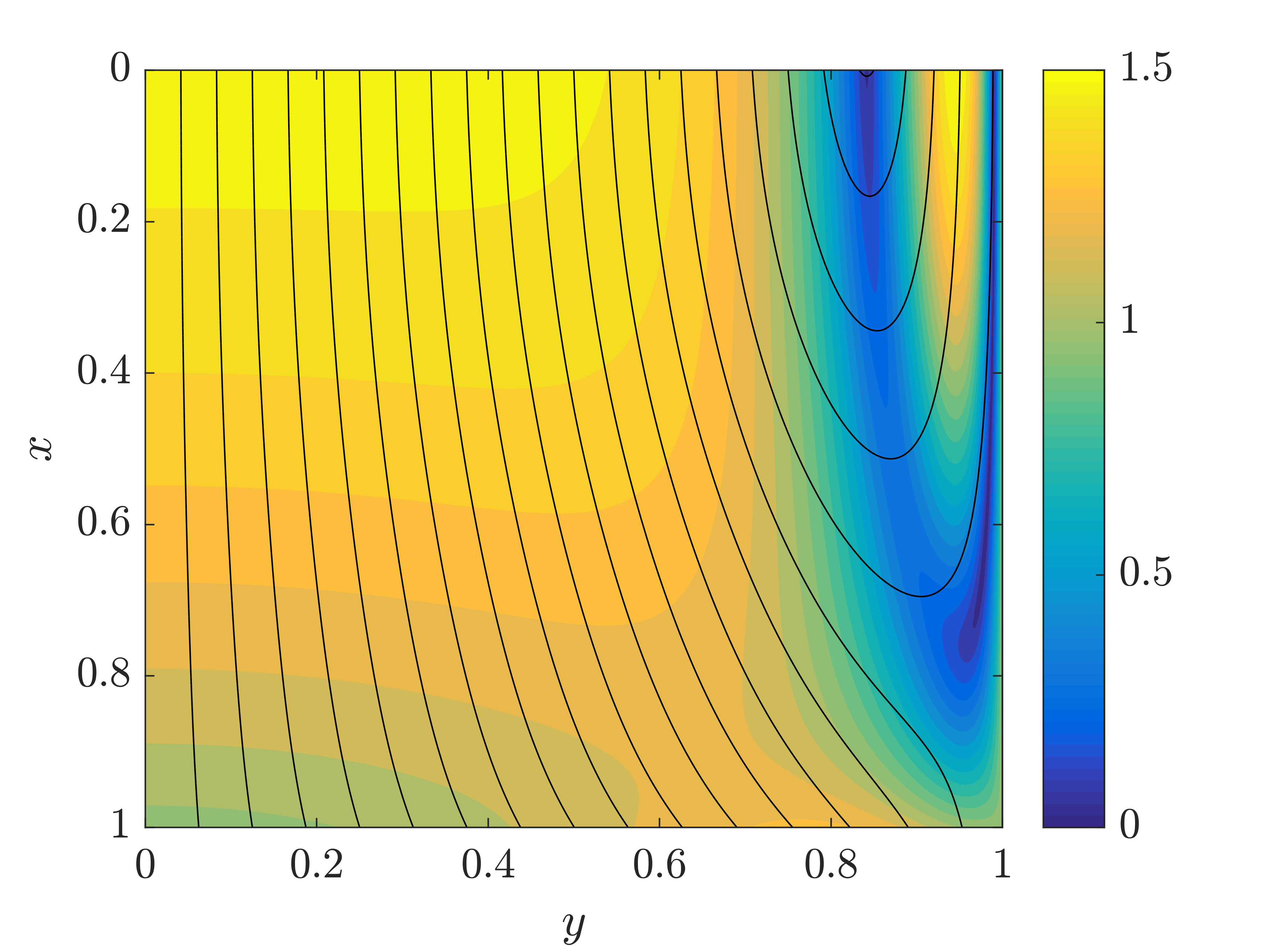
Figure 5: Velocity streamlines with velocity magnitude contours for imposed quadratic temperature profile, representing the interaction between the high viscosity paste (cylinders) and the low viscosity paste (softened material on the sides of the casing).
When these regions become too large, they can transport paste of high temperatures to the top, creating a so called viscous swamp, that can cause the cylinders to sink instead of deform and soften into the casing. Hence, although we have not included the free boundary corresponding to the position where the paste touches the casing for the first time, the size and appearance of the recirculation zones determine in this model when the Søderberg electrode is operating correctly, at least in the top region. Alternatively we can also look at the temperature problem using the flow solution, which we show in the contour in Figure 6.
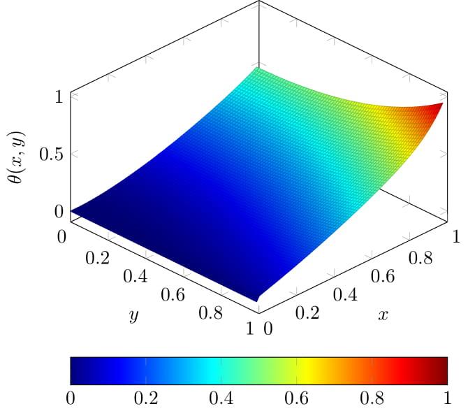
Figure 6: Temperature contours with imposed velocity profile for the case when the equivalent velocity of the cylinders at the top is higher than the slipping velocity imposed by the movement of the casing, creating recirculation zones and the hottest region at the bottom of the domain, on the casing.
In this case, note that the highest temperature occurs essentially at one point, which is where our domain ends on the casing. We have proved that in order for our system to have solutions, we must impose an additional temperature condition at this point. In practice, this condition depends on the baking, which happens below our domain. This provides us with the framework to incorporate the baking of the electrode in a way that it is directly coupled to the softening of the paste, confirming that even though the baking process happens when the electric current is applied to the electrode, any issues with the softening process will have a significant impact on the resulting electrode.

