

Electrical current distribution in a silicon furnace
- Researcher: Ellen Luckins

- Academic Supervisors: Robert van Gorder, James Oliver, and Colin Please
- Industrial Supervisors: Ben Sloman, Aasgeir Valderhaug
Background
Silicon is produced industrially in a submerged arc furnace, in a reduction reaction of quartz (containing silicon dioxide) with carbon materials. The energy for the highly endothermic chemical reactions is provided by passing an electric current through the material bed. An illustration of a submerged arc furnace for silicon production is shown in Figure 1.
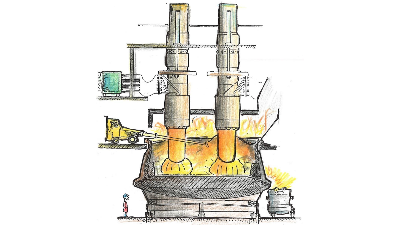
Figure 1: A sketch of a silicon furnace. Reproduced from The Si Process Drawings, by Thorsteinn Hannesson.
The electric current is provided by electrodes, and a crater of hot gases forms around the base of each electrode, through which much of the current passes as an electric arc. This arc is a region of very hot gases, ionised to a plasma, with the ions and electrons carrying the current from the electrode to the base of the furnace. This is the hottest region of the furnace, and the most energy-intensive chemical reactions occur in the material bed – known as the charge material – immediately surrounding the crater.
The electrical, thermal, chemical and material flow processes in the furnace are tightly coupled, and the physical phenomena occur over a wide range of timescales, from the heat transfer in the arc, on milliseconds, to the hours or days it takes for raw materials to flow through the furnace and be consumed in the reactions. This makes it very difficult to simulate the furnace behaviour, or to understand how these processes interact. The aim of this project is to develop relatively simple models for the coupled electrical, thermal and chemical processes within the furnace, in order to better understand the interaction between the various mechanisms.
Outcomes
We have investigated several aspects of the silicon production process. Firstly, we have studied the tightly coupled electromagnetism, fluid flow, and heat transfer in the electric arc. Using a magnetohydrodynamic (MHD) model, we have simulated a quasi-steady electric arc.
 and electrical conductivity (colour, with units S/m) through the electric arc, for a tall thin arc (left) and a much shorter arc (right).")
Figure 2: Simulated current flow (streamlines) and electrical conductivity (colour, with units S/m) through the electric arc, for a tall thin arc (left) and a much shorter arc (right).
Dimensional analysis of the MHD arc model suggests radiation is a dominant heat loss mechanism. Motivated by this, we have proposed a new, very simple model for the overall resistance of the arc, with heating due to Ohmic heating, and heat losses due to radiation only. Unlike the empirical arc-resistance models commonly used in the metallurgy literature, our arc model is simple, based on first principles, and – when coupled into an electrical circuit system for the whole furnace - captures more of the arc behaviour seen in practice.
Secondly, we have explored the asymptotic structures within the material bed. In particular, we have investigated the effect of the counter-current flow of hot gases through the porous material bed on the rate of the chemical reactions.
Our asymptotic analysis allow us to derive much reduced models for the overall evolution of the material bed in this idealised geometry and chemical system.

Figure 3: illustration of the counter-current model in the material bed of the furnace. Solid material flows right to left, heats up and reacts away to form hot gases, which flow in the opposite direction, heating up the solid material.
Finally, we have developed models coupling the electrical current conduction with the dominant chemical processes and heat transfer mechanisms, in an idealised furnace geometry. This model is a combination of our simple arc model and the counter-current model for the raw material bed. We have exploited the different timescales in the model through a multiple-scales homogenisation analysis, whereby we have derived an averaged free-boundary model for the slow flow of material through the furnace, whilst rigorously taking into account the millisecond variations in the electrical system due to the alternating current. We have found that there is a minimum current that must be applied in order that steady state solutions exist. For certain parameter regimes there are two steady states for the furnace, with only one stable, while in others there is only one.
 of our model as a function of the applied current. In one parameter regime we find only one such steady state, while in the other there are two.")
Figure 4: Bifurcation diagram showing the crater size in the steady state solution(s) of our model as a function of the applied current. In one parameter regime we find only one such steady state, while in the other there are two.